
Most guides to HDPE fittings are a list of shapes: elbow, tee, reducer, cap. That is the least useful way to sort them, because a 90° elbow exists in five different forms — moulded butt fusion, moulded electrofusion, fabricated from pipe segments, moulded socket fusion for small bore, and mechanical — and the choice between those five is the real decision. The shape follows from the drawing; the family follows from the pressure, the diameter, the equipment on site and whether anyone will ever need to take the joint apart.
So this guide is sorted by family. For each one it gives the size range, how the joint is made, what the joint is worth in pressure terms, and the mistake we see most often with it. The flange section has the bolt-pattern table that every other guide leaves out, and the fabricated section has the derating factors that most catalogues print in small type. The last section is a single selection table you can pin to the wall.
The four ways PE joins
Every fitting in this guide uses one of four joints. Butt fusion melts two prepared faces and presses them together; the fitting has plain spigot ends the same diameter as the pipe. Electrofusion melts the pipe surface from a heating coil moulded into the fitting's socket; the pipe slides in, current flows, the two surfaces fuse. Both are monolithic joints: correctly made, the joint is polyethylene all the way through and is stronger than the pipe wall. Flanged joints bolt a PE stub end against a mating flange with a gasket between; mechanical fittings compress a grip ring and seal onto the pipe outside. Both are seals rather than welds, and both can be dismantled, which is exactly why they exist.
| Method | Usual size range | Needs on site | Joint versus pipe | Dismantle? | Where it fits |
|---|---|---|---|---|---|
| Butt fusion | DN63 – DN1600 and above | Fusion machine with facer and heater plate, power, a dry tent | Monolithic; stronger than pipe when made to ISO 21307 | No | Main runs, large bore, any pressure class |
| Electrofusion | DN20 – DN800 (couplers); saddles to DN1200 main | Control box, scraper, clamps, power | Monolithic; fitting rated to pipe PN | No | Branches, repairs, tie-ins, tight trenches, any size where the machine cannot reach |
| Socket fusion | DN16 – DN125 | Heated tool with socket and spigot faces | Monolithic | No | Small-bore plumbing and service lines; rare on mains |
| Flanged (stub end + backing ring) | DN50 – DN1600 | Spanner, torque wrench, gasket | Rated by the flange class, not the pipe | Yes | Valves, pumps, meters, steel and ductile-iron transitions |
| Mechanical / compression | DN16 – DN110 (a few designs to DN315) | Hands, sometimes a wrench | Rated by the fitting, typically PN10–PN16 | Yes | Service connections, temporary works, repairs without power |
Moulded fittings: the default for anything under DN400
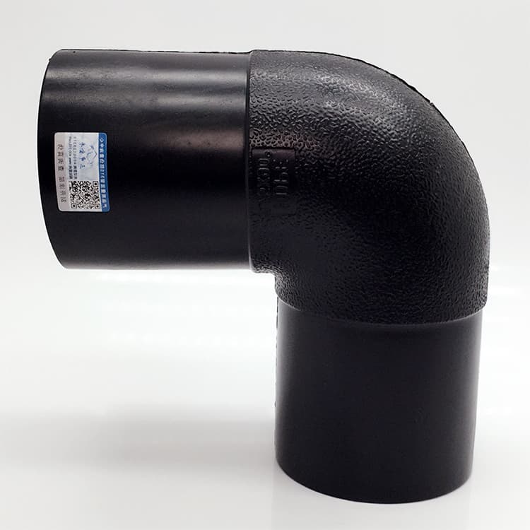
Injection-moulded fittings are made in one shot from the same PE100 compound as the pipe, in a steel mould, with a wall at least as thick as the pipe's. They carry the full pressure rating of the SDR they are made to, with no derating, and they are cheap in the sizes where moulds exist — roughly DN20 to DN400 for elbows and tees, up to DN630 for some reducers and stub ends. Above that the mould cost is not recovered and fittings are fabricated instead.
- Elbows at 90° and 45°, occasionally 22.5° and 11.25° for gentle line changes. Long-radius moulded elbows exist to DN315 for lines that will be pigged or lined.
- Equal tees and reducing tees. A moulded tee is rated at the full pipe PN; a fabricated one is not (see the next section).
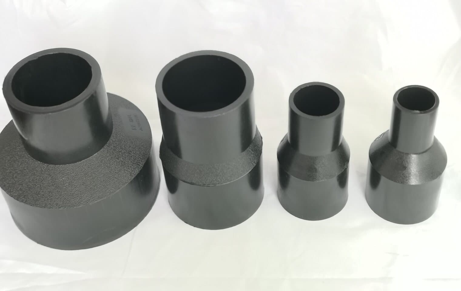
- Concentric reducers, one or two sizes down. Stepping from DN315 to DN160 in one fitting is possible but usually done in two.
- End caps for test heads and dead ends, stub ends for flanges, and saddle fittings that fuse onto the outside of a live main for a branch.
Fabricated fittings and the derating that comes with them
From about DN400 up, and for any geometry the moulds do not cover, fittings are fabricated: pipe is cut into segments and butt-welded into bends, or a hole is cut in a pipe body and a branch welded in for a tee. The welds are as strong as the pipe. The geometry is not. A mitred segment concentrates stress at the inside of each weld, and a branch cut into a pipe body removes wall exactly where the hoop stress is highest. Standards and manufacturers deal with this by derating: the fabricated fitting is rated at a fraction of the pipe PN unless it is reinforced or made from a thicker wall.
| Fitting | How it is made | Typical pressure factor | How to keep the full PN |
|---|---|---|---|
| Segmented bend, ≤ 7.5° per segment | Pipe cut and butt-welded in several mitred segments | 0.8 × pipe PN, some makers 1.0 with fine segments | Use more, smaller segments or one SDR thicker |
| Segmented bend, 15° – 22.5° per segment | Fewer, sharper mitres | 0.5 – 0.8 × pipe PN | Avoid on pressure mains; use for gravity and low-pressure lines |
| Fabricated equal tee, unreinforced | Branch welded into a hole cut in the run | 0.5 × pipe PN | Fabricate from one SDR thicker, or use a moulded or reinforced tee |
| Fabricated reducing tee, branch ≤ half run DN | Small branch into a large run | 0.7 – 0.8 × pipe PN | Electrofusion saddle instead of a cut-in branch where possible |
| Fabricated cross | Two branches into one run | 0.5 × pipe PN or lower | Two tees in series, or a moulded manifold |
| Flanged spool with stub ends | Stub ends butt-welded to a pipe length | 1.0 × pipe PN (the flange sets the joint rating) | Match backing ring class to line pressure |

Electrofusion: the fitting that fixes what butt fusion cannot reach
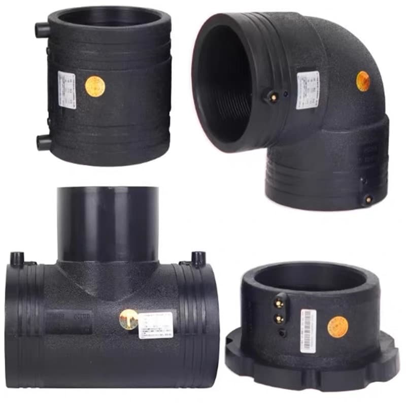
An electrofusion coupler is a moulded PE sleeve with a resistance wire wound into its bore and two terminal pins on top. The prepared pipe ends slide in, a control box passes a set voltage — 39.5 V on most systems — for a time read from the barcode on the fitting, the wire heats, the pipe surface and the coupler bore melt together, and a fused zone forms along the whole length of the coil. Indicator pins rise to show the melt has reached the surface. It is the only monolithic joint that can be made on a pipe that cannot be moved: in a trench too narrow for a machine, on a live main under a saddle, at a tie-in where the two ends are already fixed.
- 1
Cut square and mark the insertion depth
The pipe end must reach the centre stop or the fitting's marked depth. Short insertion leaves part of the coil heating air, and that joint will leak under test.
- 2
Scrape the whole fusion zone
Remove 0.2 to 0.4 mm of oxidised skin with a rotary scraper — not sandpaper, not a knife. Fresh polymer fuses; the weathered surface does not. Scrape marks should be visible over the full insertion length.
- 3
Clean with an approved wipe and do not touch
Isopropanol on a lint-free wipe, then hands off. A fingerprint is a release agent.
- 4
Clamp for alignment and against movement
The pipe must not move during fusion or cooling. Alignment clamps hold the ends coaxial; misalignment of more than 10 % of the wall shows as a cold side.
- 5
Fuse to the barcode, cool to the label
The control box reads fusion time from the fitting's barcode (ISO 13950) and adjusts for ambient temperature. Cooling time is printed on the fitting and is not negotiable; releasing clamps early is the second most common cause of failure after poor scraping.
- 6
Record the joint
Modern boxes log every fusion: fitting code, time, voltage, ambient. That log is the joint's certificate. Ask the contractor for it.
Flanges: stub end, backing ring, and the bolt pattern
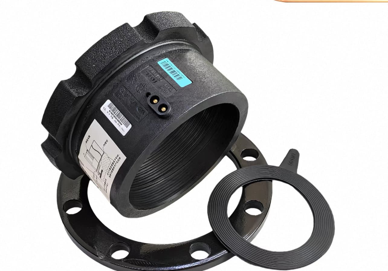
PE cannot be threaded or welded to metal, so every connection to a valve, pump, meter or steel pipe is flanged. The PE part is a stub end (flange adapter): a short moulded or fabricated spigot with a thick collar, butt- or electro-fused to the pipe. A loose metal backing ring — steel, galvanised or coated, occasionally stainless — sits behind the collar and takes the bolts. The joint rating is the flange's rating, not the pipe's: a PN16 backing ring on PN10 pipe is fine, the reverse is not. The bolt pattern must match the mating metal flange, and that is where a table earns its place.
| PE pipe DN (OD, mm) | Flange nominal size | Bolt circle PCD (mm) | Bolts, PN16 | Gasket type |
|---|---|---|---|---|
| 63 | DN50 | 125 | 4 × M16 | Full-face or IBC, EPDM/NBR |
| 90 | DN80 | 160 | 8 × M16 | Full-face, EPDM/NBR |
| 110 | DN100 | 180 | 8 × M16 | Full-face, EPDM/NBR |
| 160 | DN150 | 240 | 8 × M20 | Full-face, EPDM/NBR |
| 225 | DN200 | 295 | 12 × M20 | Full-face with steel insert recommended |
| 315 | DN300 | 410 | 12 × M24 | Full-face with steel insert recommended |
Mechanical and compression fittings
Compression fittings — a body, a grip ring, an O-ring seal and a nut — join small PE pipe with no heat and no power. Push the pipe in, tighten the nut, done. They are rated by the maker, usually PN16 to DN63 and PN10 above, and they are the right answer for service connections off a main, meter installations, irrigation laterals, and any repair where a fusion crew is not coming. Their limits are real: the seal is an elastomer with its own life, the grip ring can score the pipe if over-tightened, and end-load resistance depends on the design — some are end-load-bearing, some are not, and a compression coupler that is not will pull off a straight run under pressure unless the pipe is anchored. Above DN110 they exist but are rarely economic against electrofusion.
Transition fittings deserve a separate mention: a PE spigot factory-fused to a brass or steel threaded end, so that a PE service pipe can screw into a meter or a metal valve without a flange. They are the standard way a house connection meets the metalwork and are made to DN63 in most markets.
Choosing: one table
| Situation | First choice | Why | Avoid |
|---|---|---|---|
| Straight main, DN63 and up, open trench | Butt fusion pipe-to-pipe; moulded butt fusion elbows and tees | Cheapest joint per metre, full PN, no fittings to stock beyond the changes of direction | Compression couplers on the main |
| Main above DN400 | Butt fusion with fabricated bends from one SDR thicker; moulded stub ends | Moulds do not exist; thicker wall recovers the derating | Unreinforced fabricated tees at full PN |
| Branch off an existing main | Electrofusion saddle (tapping or branch) | Fuses to the outside; no cutting the main, can be done live | Cut-in fabricated tee on a live line |
| Repair in a narrow trench | Electrofusion coupler | Only monolithic joint that needs no room for a machine | Butt fusion (cannot reach); compression above DN110 |
| Connection to valve, pump, meter or steel | Stub end + backing ring, class matched to the metal flange | Only dismantlable full-bore joint | Threaded PE (does not exist reliably); mismatched PCD |
| Service pipe DN20 – DN63 | Compression or transition fitting | No power, no training, fast; PN16 rated | Butt fusion (too small to face properly) |
| Line that will be dismantled or extended later | Flanged spools at the break points | Flanges come apart; fusion does not | Fusing everything and cutting later |
The order of preference is almost always the same: fuse where you can, electrofuse where you cannot reach, flange where you must come apart, compress where the pipe is small and the crew is not a fusion crew. A specification that says which of those applies at each node — and gives DN, SDR and PN for every fitting — is one that can be quoted, stocked and built without anyone guessing.
Sources and standards
- ISO 4427-3: Polyethylene pipes and fittings for water supply — Fittings
- EN 12201-3: Plastics piping systems for water supply — Fittings
- ISO 21307: Butt fusion jointing procedures for polyethylene pipes and fittings
- ISO 13950: Electrofusion fittings — Barcode data for automatic control
- EN 1092-1: Flanges and their joints — Steel flanges, PN designated
- Plastics Pipe Institute — Handbook of Polyethylene Pipe, chapter 9 (joining)