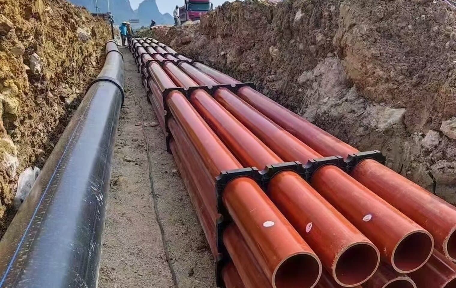
Almost every buried PE pipe that has been dug up deflected, cracked at a fitting or ovalled beyond the limit had the right pipe in it. What it did not have was the right soil around it. Polyethylene is a flexible pipe: under load it deflects a little, pushes sideways against the soil at its haunches, and the soil pushes back. That pipe–soil system is what carries the traffic and the cover. Remove the soil support — leave a void under the haunch, backfill with clay lumps, drive over it before it is compacted — and the pipe is carrying the load alone, which it was never designed to do.
This guide is written for the crew and the inspector. It follows the trench from the bottom up, gives the numbers that matter at each layer, and says which standard the number comes from so it can be checked against the project specification. Where ASTM and EN differ, both are given.
Why a flexible pipe cares about soil and a rigid one does not
Load on a buried pipe comes from the soil column above it and from anything moving on the surface. A rigid pipe resists by wall strength alone and is designed for a bedding factor. A flexible pipe deflects under that load; as it flattens, its sides move outward into the embedment soil, and the soil's passive resistance takes over most of the load. In a well-compacted granular embedment, the soil carries the majority of the vertical load and the pipe's ring stiffness matters comparatively little. In a poorly placed one, the pipe carries far more than its share.
Deflection ≈ (K · W) / (0.149 · PS + 0.061 · E′)
the Iowa formula in its simplest form: K is a bedding constant (about 0.1), W the load per unit length, PS the pipe stiffness and E′ the modulus of soil reaction. For PE pipe the E′ term dominates — soil quality, not pipe stiffness, sets the deflection.
Trench width and depth
The trench needs to be wide enough to place and compact embedment at the sides of the pipe — not wider. A wider trench does not help the pipe and costs money to fill. The minimum is set by the width of the compaction equipment that has to work in the haunch, which is why the number grows with pipe size.
| Nominal size | Minimum clear width | Basis |
|---|---|---|
| DN ≤ 110 | OD + 300 mm | Room for a hand tamper each side |
| DN 125 – 400 | OD + 400 mm | ASTM D2321: greater of OD + 400 mm or 1.25 × OD + 300 mm |
| DN 450 – 900 | 1.25 × OD + 300 mm | ASTM D2321; allows a walk-behind plate compactor each side |
| DN > 900 | OD + 600 mm | EN 1610 Table 1 for pipes over 700 mm |
Depth of cover is the other half. Under fields and footpaths, 600 mm to the pipe crown is the common minimum; under roads it rises to 900 mm to 1.2 m depending on the authority, because the pipe must be deep enough for the load from a wheel to spread before it reaches the crown. Shallower cover under traffic is possible with a concrete or a compacted-granular bridging slab, but it has to be designed, not improvised.
Bedding: 100 to 150 mm, and never rock
The trench bottom is graded to line and level, and any rock, boulders or hard spots are removed and replaced. The bedding layer — 100 mm minimum for small pipe, 150 mm for pipe above DN400, and 150 mm minimum over rock — is placed and compacted before the pipe is laid. Its job is to give the pipe uniform support along its full length. A pipe that rests on two high spots with a gap between them is a beam, and polyethylene is a poor beam.
- Material: ASTM D2321 Class I (crushed stone 6–20 mm) or Class II (clean sand and gravel). No clay, no organics, no frozen material.
- Maximum particle size in the bedding and embedment: 20 mm for pipe up to DN400, 25 mm above. Large stones under a pipe are point loads that stay there for fifty years.
- In groundwater, use crushed stone rather than sand, and dewater the trench before laying. Sand placed in standing water does not compact, it liquefies.
Haunching and embedment: the layer that does the work
Once the pipe is on the bed, the haunch zone — the wedge between the bed and the pipe's springline on each side — has to be filled and compacted. This is the hardest part of the job to do well because the space under the curve of the pipe is awkward to reach, and it is the most important, because that is the soil the pipe leans on. Voids left here are the single most common cause of excessive deflection.
- 1
Place in lifts of 150 mm
Shovel-slice the material under the haunch so it fills the wedge, then compact each lift with a hand tamper or a narrow vibrating plate. Do not dump a full trench depth and compact from the top; the material bridges over the haunch and leaves a void.
- 2
Work both sides together
Bring the embedment up on both sides of the pipe in the same lifts. Filling one side first pushes the pipe sideways off its line and can lift it off the bed.
- 3
Carry embedment to 150–300 mm above the crown
The initial backfill continues past the top of the pipe by at least 150 mm (ASTM D2321) or 300 mm where heavy compaction equipment will follow, so the crown is protected from the compactor and from stones in the final backfill.
- 4
Compact to the target, not to a feel
85 % Standard Proctor (ASTM D698) is the minimum for embedment under fields; 90 % is normal practice; 95 % under roads and wherever the project specification says so. A nuclear density gauge check per 50 m of trench is cheap insurance.
Initial and final backfill
| Class | Material | Bedding and haunch | Initial backfill | Final backfill |
|---|---|---|---|---|
| I | Crushed stone, angular, 6–20 mm | Preferred | Yes | Yes |
| II | Clean sand and gravel, < 12 % fines | Yes, compacted | Yes | Yes |
| III | Sand and gravel with 12–50 % fines | Only with controlled moisture and compaction | Yes | Yes |
| IVA | Silts and clays, low plasticity | No | Only in dry conditions with compaction | Yes |
| IVB / V | High-plasticity clays, organics, frozen soil | No | No | No |
The final backfill carries no structural duty toward the pipe; its job is to restore the surface. That is why native material is normally fine for it and why the particle-size limit relaxes. What it must not do is deliver a boulder onto 150 mm of embedment above the crown. Where the excavated material is unsuitable — wet clay, rubble — the cost of importing granular fill for the whole trench is small against the cost of digging the pipe up.
Rock, groundwater, roads and heat
- Rock trench: over-excavate 150 mm below the pipe and bed on Class I stone; never lay directly on rock or on a trench bottom that has rock protruding.
- Groundwater: dewater to below the bedding before laying, use crushed stone embedment that drains, and consider a geotextile between embedment and native soil where fines could migrate and wash out the support.
- Under roads: cover to the authority's minimum, 95 % Proctor throughout the embedment and the final backfill, and no pipe crossing left with loose fill under a running lane even overnight.
- Heat: PE expands and contracts about 0.18 mm per metre per °C. Pipe laid in the sun at 40 °C and backfilled will pull on its fittings when the ground cools it to 15 °C. Snake the pipe gently in the trench, backfill in the cool of the day where possible, and never anchor both ends before the pipe reaches ground temperature.
Test before you close the trench
For pressure pipe, the hydrostatic test is run with the joints exposed and the pipe barrel backfilled — the embedment restrains the pipe against movement under pressure, the exposed joints let you see a leak. For gravity pipe, a deflection gauge or a mandrel of 95 % of the bore pulled through after backfilling proves the installation; a mandrel that sticks tells you where the haunch was left hollow, which is a great deal cheaper to learn now than at handover.
Sources and standards
- ASTM D2321: Underground installation of thermoplastic pipe for sewers and other gravity-flow applications
- ASTM D2774: Underground installation of thermoplastic pressure piping
- EN 1610: Construction and testing of drains and sewers
- Plastics Pipe Institute — Handbook of Polyethylene Pipe, chapter 7 (underground installation)
- AWWA Manual M55: PE pipe — design and installation